
Hand Prosthesis
INTRODUCTION
Back to 2017. This project was assigned by the University of Leuven and belonged to one of my school subjects. In a team of six members we had the task to realize a hand prosthesis on real scale which should replace the functionality of a human hand and wrist. The prosthesis must as well be capable of holding a balloon, a pencil and an object with an irregular shape, like a potato. It also should be able to pour liquid out of a can in a glass. All within a budget of 250 euros and the time of only three months.
The fingers and the body of the arm are 3D printed. The palm of the hand is a five-layered design of laser cutted acryl. All parts are assembled using different screws, nuts and washers. Each finger can be bend by the use of one servo motor inside the body, and a nylon rope in between. A sixth servo motor rotates the wrist over 270° by using a gear transmission and the support of two ball bearings. Some foam rubber is attached on the palm and the fingers to create more grip.
The prosthesis is designed for an amputation of the right hand and can be controlled in two different ways. The main control is a glove around the user's left hand. The glove consist of several flex sensors and one accelerometer, so the (right-handed) prosthesis is able to imitate the movements of the glove. This idea was based on my past project 'Hand controlled car'. An alternative way is a console, where all five fingers and the wrist can be controlled with potentiometers. Both controls can be plugged into the prosthesis by using a 10-pole flat cable. An Arduino determines which method is being used, and subsequently to calculate the signals to all six servos. A 3-cell LiPo battery is used to have a power supply for all the electronics on board. We obtained for a buck converter to reduce the supply voltage (around 11.1 Volts) to 5 Volts.
Foto Handprothese geheel
3D PRINTING
"3D printing is an additive manufacturing process that creates a physical object from a digital design." - www.3dhubs.com/what-is-3d-printing. Honestly, I can't give a better definition to 3D printing than this website does. 3D printing is, however, not always as easy as you would expect. The struggle begins when you need to print thin creatures or overhanging elements. The trick is here to always design your parts in a way it is easy to print for a regular 3D printer. I love the Ultimaker 3: precise, fast, and the possibility to print your support material in PVA (thanks to its dual extender). This paragraph is kind of a 'blog' - in contrast to all other subjects on this website - about how we manufactured the most difficult parts of the prosthesis. All parts are printed in PLA.
Body
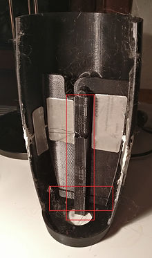
The body of the prosthesis had some crucial overhanging elements to print. In general, this can be solved by adding support underneath (encircled in red in the first picture). However, this solution causes another problem, namely that this support will stick to your design if it's also printed in PLA. There will always be some damage visible after breaking the support apart. First, the body was printed in this way and the result can also be seen in this picture. The support was really hard to break carefully, and the print in general also wasn't a succes. The printer suddenly stopped printing for a while in the middle of the process, what resulted in a broken print. We tried to hold the two seperate parts together with some aluminium plates at the inside, and we painted the outer shell grey. But unfortunately, this print couldn't be used in the project. The difference with a new print is showed in the second picture.
.jpg)
.jpg)
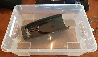
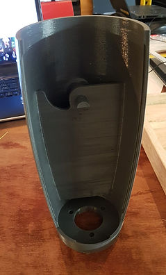
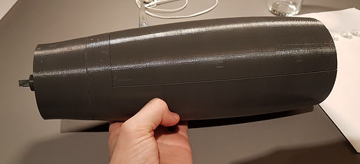
The second and final print of the body is done with another printer, in particular the Ultimaker 3 Extended. This printer has the advantage that the support material can be printed in PVA: a material that doesn't stick to PLA, and can be removed easily by drowning it into water. The PVA is the white material in the first picture below. The second picture shows the PVA dissolving in water, while a weight on top prevents the print from floating up to the surface. It leaves a stunning result as you can see in the last two pictures. Note: You can see a so called 'brim' around the body in the first picture. This brim is used to create more adhesion between the print and the printing bed. Otherwise, the edges of the print touching the bed could raise a bit. A brim can be easily removed when the print is done.
.jpg)
.jpg)
.jpg)
.jpg)
Cover
The cover is designed to open and close the body easily. It protects all the electronics inside the body from the environment, and gives the prosthesis an impressive look. The cover is also printed with the Ultimaker.
.jpg)
.jpg)
Extension
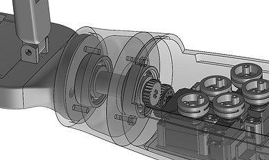
The aim of this part is a bit hard to explain, but I will give it a try. There are several reasons why we didn't design this small part together with the body in one final part. First of all, the body would become too tall to print it in one time... On the other side, it wouldn't even be possible to assemble the bearings into the prosthesis if the extension wasn't a seperate part. The sketch at the right gives an idea of the inside.
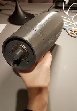
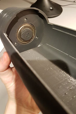
The assemble went as follows. First, one bearing was placed and fixed into the body. Next, the shaft was fixed through the first bearing. This result can be seen in the first picture. Next, the second bearing was placed into the extension, and afterwards the extension was pushed over the shaft, through the second bearing. At the end, the extension is fixed on the body with three small bolts. The final result is shown in the two last pictures.
.jpg)
.jpg)
.jpg)
Servo holder
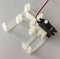
All six servo's are fixed inside the body by a self-made holder which you can see at the following two pictures. The holder is designed in such a way that all servo's are as close as possible to each other in order to use as less as possible space inside the body. The holder is printed in white PLA (not PVA) with a simple Velleman Vertex printer. These printers have a really bad quality, but their prints are usefull for easy prints like this.
.jpg)
.jpg)
Summery
-
Always look for a 3D printer that meets your requirements. If your design has some crucial overhanging element, find a printer that allows you to print the support in PVA.
-
Bla bla
-
LASER CUTTING
"Laser cutting is a precise method of cutting a design from a given material using a CAD file to guide it." - www.cutlasercut.com/getting-started/what-is-laser-cutting-laser-cutting-process. Alright, but what material are we speaking about? Most common materials are flat objects, like plates of MDF, acrylic (PMMA), cardboard, etc. The CAD file is a 2D (not 3D) drawing and represents the cutting lines that the laser has to follow during the cutting process. Laser cutting is one of my favourites when it comes down to fast and cheap processes, like prototypes or constructions you need for an experiment or similar. If a project consists of different laser cutted objects (like the palm of the hand prosthesis in this project), I will certainly make my first designs in MDF. When I'm sure that all (MDF) cutted objects fit the design, I will often cut the final design in acrylic, because acrylic is much stronger and looks much better than MDF. But always remember that acrylic is more expensive.

Acrylic - PMMA
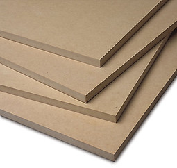
MDF
How to draw the CAD file?
One specific software you certainly need is 'Inkscape'. In this software you can draw easy objects like rectangulars, circles, et cetera which you can send immediately to the laser cutter. Remember that if you want to CUT a line, you need to color this line RED. If you color a line or area BLACK, then the laser cutter will ENGRAVE this line or area! All lines should also be set to a thickness of 0.05 mm.
Foto document in Inkscape die klaar is voor gebruik
There are many tutorials you can find on the web on how to work with Inkscape itself, so I will explain nothing about this. What I want to teach you is how you can easily export 2D drawings from your 3D model so you can import them into Inkscape. I always use 'Solidworks' for my 3D models, so I explain the steps from this software.
-
Right click on the surface you want to export and click 'Export to DXF / DWG'. Choose a location to save the file on your computer and make sure you save the file as .dxf. Click the save button.
-
After saving, you will be redirected to Solidworks again. On the left, a window will appear with the name 'DXF / DWG Output'. If you want to get more surfaces in one export, you can add surfaces by just clicking them. Make sure that all surfaces you add are parallel or planar to the first surface, otherwise you will get an error message.
-
Click the green check mark. A new screen will appear with all selected entities. Click the save button. The DXF file will be saved on the location you have chosen in step 1.
-
Open Inkscape. Go to File and choose Import (Or simply use Ctrl+I). Search for the DXF file you just made and click Open. A new screen will appear. Simply just click Ok, but make sure that the scaling factor is set to 1.0. Now your entities from Solidworks will be imported. If you use a student license of Solidworks, you will see that a text 'SOLIDWORKS Educational Products, For Instructional Use Only' will appear over the drawing. Simply right click the imported file and 'raise group'. Now you can delete the text seperately.
Foto's behorende bij vorige 4 stappen uit Solidworks als voorbeeld de palm.
GEAR TRANSMISSION
A gear transmission or gear drive is one of the three possibilities to create a mechanical power transmission (= the way to transmit power from one shaft to another). First of all, we have the belt drives: the shafts are connected by an endless belt passing over the shafts. The connecting belt is kept in tension so that motion of one shaft is transferred to the other without slip. Similar to the belt drive is the chain drive. The only difference is here that we use a chain instead of a belt (of course). A belt drive is less noisy, but a chain drive is much stronger. It's up to you to decide if the transmission within your project has to be silent or strong in the first place. I will not discuss these types in detail, but don't hesitate to contact me if you have further questions about it.
.jpg)
Old belt drive where the belt is passing over the shaft of a generator.
.jpg)
Chain drive on a bicycle.
A gear drive is somehow a chain drive, but without the chain, and where both gears are directly connected with each other. Likewise, this transmission is cheaper and less noisy than a chain drive. It's a popular transmission in mechatronics, and further on I will explain how to dimension and make your own gears.
.jpg)
Multiple gear transmissions (gear train) in a mechanical machine.
Fundamental concepts every engineer should know.
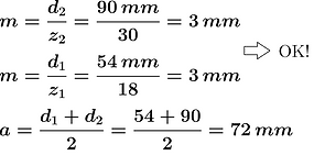
A gear contains three important concepts: pitch diameter d, number of teeth z and modulus m. They are related via the following formula: d=m·z. It's important to remember that both gears of a gear drive should have the same modulus! Alright, we already understand m by its definition (see formula) and z. But what about d, the pitch diameter? Generally, the pitch circle (that is the circle with diameter d) is the imaginary circle that rolls without slipping with a pitch circle of another gear. In a more practical way will d be equal to the center distance a between two identical gears (same d and z)*. Difficult, I know, but don't worry about it too much. I made the following sketch (of two different gears!) with a numerical example to illustrate these concepts.
.png)

*If both gears are identical, we can say mathematically that d1=d2=d. Then the formula above this sentence tells us that a must be equal to d.
Additional: The spiraling curve of a tooth profile is called an involute. The involute of a circle starts unwinding itself from a stationary circle called the base circle. The diameter of a gear's base circle is typically equal to the pitch diameter multiplied by cos(20°) (and is thus always smaller then the pitch diameter). An involute gear profile is the best profile we can design to be sure that the angular velocity ratio between two gears remains constant throughout the mesh. The following GIF will make everything more clear.
Source:
en.wikipedia.org
How to dimension your gears?
-
Most of the time is the distance a fixed due to your design. Also the transmission ratio i (= the gear ratio as defined in the equation next to the sketch) is known. From these two equations we can calculate d1 and d2.
-
The next step is to look for the number of teeth z. Because we are making our own gears, the modulus is a free decimal number and we can make a guess for z1. Choose z1 greater than 14 and calculate the modulus m of your design.
-
Now you are able to calculate z2. Make sure z2 and z1 are rounded numbers! If this is the case, you're done. But most of the times will z2 not be a rounded number from your calculation. Option 1: Retake step 2 and choose another value for z1 in such a way that z2 will be a rounded number. Unfortunately, this option will probably fail. Option 2: You can try to round z2 up or low, and calculate from here the new value for d2. But now, a and i aren't respected, and the gears won't fit anymore. There are two solutions: you can use the method of profile shifted gears (but that's a bit too extreme calculation for a beginning engineer) OR you can simply try to adjust a (and i) in your design. I did the same in the wrist of the prosthesis and I will give you some numerical results of this last solution.
Foto calculation (of typen)
How to make your gears?
For instance, we have two options: 3D printing or laser cutting. A while ago I have manufactured many samples of gears using both 3D printing and laser cutting. The final result is that laser cutting in acrylic is far way the best option. Unfortunately, 3D printing small gears with a regular 3D printers (even with an Ultimaker 3) isn't precise enough.
As you may have seen already has the gear transmission of the wrist in the hand prosthesis been, however, 3D printed. We wanted to have the shaft and the gear in one piece to avoid extra parts to mount them together. 3D printing the gears was only possible when the pitch diameter became big enough, so you can assume the following dimensions as a limit where 3D printing gears becomes possible.
If you want to make gears by your own, you can use my Solidworks file where you can give in your values for d and z in 'Equations', Solidworks will do the rest. If you don't have Solidworks or you have any problems to design or make them by your own, you can always contact me. You give me your dimensions, and I'll give you the document you need to import in Inkscape. Check the paragraph 'Laser cutting' above to learn how you can import DXF files in Inkscape.
Foto's voorbeelden zelfgemaakte tandwielen + foto voorbeeld in Inkcape
BEARINGS
Imagine the problem where we want to spin a wheel around a shaft as frictionless as possible, like a car wheel for example. Hence, a ball bearing is the solution and is by definition a machine element that reduces friction between moving parts. In case of the car wheel, the inner ring of the bearing is fixed on the shaft and the outer ring is fixed on the wheel. Between both rings are placed multiple spherical balls to let both rings be able to roll over each other.
Use
Text
Types
Text
SCREWS/NUTS/WASHERS
After manufacturing all parts needed to contruct your design, you always want to assemble your product as quick as possible. There are different methods to fasten the parts together: you can use glue, tape, rivets, some magic, or even better: screws! There are two types of screws available on the market: bolts and (regular) screws. The screws pictured on the left are called bolts and they always need a nut on the other side. The screws at the right takes no nut and threads directly through the material. A screw screws into something, a bolt bolts several things together. Unfortunately, bolts are also called screws in practice.
Screws
Screws - now I mean the regular screws at the right - are mostly used for wooden constructions, such as closets, some walls inside your house, roofs, garden sheds, et cetera. They are also used in plastic constructions for commonly fasten the plastic frames around a product. Think about a hair dryer, the battery caps of a calculator or a remote control of your tv. Likely, this type of screws aren't really interesting to us.
Bolts
These type of screws are making the life of a mechanical engineer so much easier, and the rest of this chapter will expand on it. The difference with a regular screw is that a bolt does not thread into the material itself, but fasten them by using a nut on the other side. This makes it possible to use bolts for every material, as thin as you want.
Use
text
ARDUINO
An Arduino is the brain or control unit of your project. This ingenious open source computer processes all incoming input signals (switch, sensor, ...) and controls all attached actuators (DC motor, LED, ...) based on a program you wrote and uploaded to. It's one of the most popular microcontroller platforms in use today. It appeals to hobbyist, engineers, and students all over the world, and provides an affordable way to get involved with embedded hardware. An Arduino simply makes your project alive.
Capabilities
Text
Use
Text
VOLTAGE REGULATOR vs.
BUCK CONVERTOR
If you want to reduce the voltage of a given power supply (e.g. a battery or power adapter), you have two options: A voltage regulator or a buck converter. When do you use which one and what are the differences between them? A buck converter is explained in the next paragraph below, afterwards a voltage regulator is discussed in detail.
Voltage regulator
A voltage regulator is the first electronic component of both that will come in mind to solve the problem. It's an easy understandable component that uses the unique characteristic of a Zener diode. I hear you thinking: A Zener diode, what is that again? Let's have a look to the differences between a regular diode and a Zener diode in general.
Diode
I explained Diodes in detail in another paragraph. You can read this chapter first if you wish. In summary is a (regular) diode an electronic component that conducts current in only one direction. This direction is also called 'forward bias'. If you try to make the current flow in the other direction ('reverse bias'), the current will be blocked and no current will flow through the diode. HOWEVER, if the reversed voltage reaches the breakdown voltage, the diode conducts anyway and tend to experience the so called 'Avalanche breakdown'. For normal diodes this breakdown voltage is around -50V to -100V, or even more negative. But what if we reache this breakdown voltage in reality? As we already know, the diode will conduct, BUT it will continue to conduct even if the voltage across it drops below the breakdown voltage again (this effect is called a hysteresis effect). Conclusion: Trying to let the current flow through a diode in reverse bias doesn't make any sense.
Zener diode
A Zener diode has exactly the same characteristic as a regular diode. So, what are the differences? A Zener diode acts different in reverse bias: it can have a much smaller breakdown voltage and does not suffer of a hysteresis effect. I'm not going to explain why this happens exactly, but in short: a Zener diode is actually a heavily doped diode where the depletion region is very narrow. In terms of a Zener diode, we generally speak of a Zener breakdown (instead of an Avalanche breakdown) and a Zener voltage (instead of a Breakdown voltage). The last two sentences contained some expensive words, but it comes down to the following conclusion: Zener diodes are made to be used in reverse bias, and their (low) Zener voltage makes them interesting as a voltage reference.

Working principle
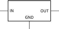
Back to the voltage regulator. Take for example a voltage regulator with a voltage output of 5V (e.g. UA7805). This involves that this regulator exists of a Zener diode with a Zener Voltage of 5V. To make you understand this line of thought, I'll take the following basic circuit of a voltage regulator.

Source:
en.wikipedia.org
Let's say again that the Zener Voltage is equal to 5V. If the input voltage Uin is lower than 5V, then there will flow zero current through the resistor R and the Zener diode D because the diode is placed in reverse bias. From the point that Uin raises from 5V to 8V for example, the Zener Voltage has exceeded and the Zener diode conducts anyway. The output voltage Uout will be equal to the Zener voltage of 5V, and the remaining 3V (8V - 5V) can be found across the resistor.
Additional: Try to understand that this basic circuit will not be useful without any further extensions. Why not? If the output is connected with a load RL (this can be everything like an Arduino, servo motor, LCD, etc.), these components will need current from the output of the voltage regulator (a so called 'current draw'). An increase in the current draw of the load can cause an output voltage drop*. These drops can turn off or reset the Arduino or whatever we have chosen as load. To avoid these drops we can use a transistor as placed in the following circuit. But now it's just getting too complicated for what you need to know about it. I continue in the next paragraph with the more practical and interesting side of a voltage regulator. The symbol of a voltage regulator can be found at the right.

Source: en.wikipedia.org
Use
If you are looking for a voltage regulator, you have to keep four things in mind: What output voltage do I need, what maximum current draw do I have, what input voltage do I have, and do I need to have a heatsink? Imagine the following situation: I have a battery of 9V and I need to get a voltage of 6V across a Parallax Continuous Rotation Servo. According to its datasheet, the servo will have a maximum current draw of 190mA (140mA + 50mA). First of all, we are looking for a voltage regulator with an output voltage of 6V. 6V isn't really a popular value, so I will take a 5V regulator. Have a look to the following three options:
Source: www.gotron.be


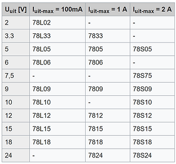
All of the regulators from above have an output voltage of 5V, so that's great. The first one (UA78L05) can deliver an output current of maximum 0,1A or 100mA, the second one (UA7805) 1A, and the third one (UA78S05) 2A. We have a maximum current draw of 190mA, so the UA78L05 can't be used. The second and third one are ok, but we will optain for the UA7805 because we don't need the extra 1A of the UA78S05 what also makes the second one cheaper. Note: You can immediately look at the package of the regulator if it can handle a low or high current draw. A TO92 will always handle low currents around 100mA, whilst a TO220 package can usually handle 1A at least. The first and second one have the same price, so why would anyone buy the first one in the row? A TO92 is smaller and if you are working on small PCB's, it can be useful to have your components as small as possible.
Alright, let's take the second regulator to solve the problem. No, wait! We must check if there are any restraints on the input voltage. Take as a general rule that the input voltage always needs to be at least 2V higher than the output voltage of the regulator, otherwise the voltage regulator will not generate the desired output voltage (it will be much lower). In case of the servo, a UA7805 will function well with a battery of 9V (we would need at least 7V = 5V + 2V). But imagine having a battery of 6V (e.g. 4 AA batteries of 1.5V in series), what should we do? The only solution is to obtain for a low-dropout or LDO regulator. These regulators still work fine with input voltages of at least 1V higher than the output voltage. So in case of the battery of 6V, an LM2940CT-5 could do the job (but they are kind of expensive in contrast to the normal ones). Additional: The table at the right shows all possible regulators you can buy. Most popular are those with an output voltage of 3.3, 5, 9, 12 and 24 Volts.

Source: nl.wikipedia.org
And what about that heatsink? Reducing 9V to 6V with a voltage regulator creates heat. And the higher the input voltage or the higher the current draw, the more heat that will be dissipated from the regulator. It can be so hot that the regulator begins to overheat and doesn't function properly anymore. We can use a heatsink to avoid overheating, and is placed against the regulator. A heatsink is nothing more than metal plates, and the more surface the heatsink has, the more he can spread the heat over its surface.
Verder uitleggen grootte van heatsink bepalen + foto heatsinks
VOLTAGE REGULATOR vs.
BUCK CONVERTOR
There is one big problem related to a voltage regulator: heat. That's due to the way it is designed: It's a simple circuit that lowers voltages by dissipating power as heat. We can regulate the heat by using a heatsink, but sometimes even the heatsink will be too hot for the environment around it. A buck converter in particular is the solution. It's another way to decrease voltage inputs with a higher efficiency which reduces the heatsinking needed.
Buck converter
A buck converter (or step-down converter) belongs to the group of DC-to-DC converters. Another important DC-to-DC converter is a boost converter (or step-up converter) and is used to increase voltage inputs (instead of decreasing!). But for now, I will only expand on a buck converter.
Text
POTENTIOMETER
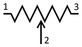
A potentiometer (also abbreviated with 'pot') acts as an adjustable voltage divider. A pot always exists of three terminals and can be seen as a three-terminal resistor like its symbol correctly represents.
Types
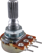
There are three types of potentiometers, where two of them are rotational pots and the other one is a sliding pot. The sliding pot isn't really popular in contrast to the rotational ones: the 'normal' rotational pots (thumb pots) and the trim pots. The trim pots have the same functionality of a normal one, but meant to be adjusted for fine-tuning an electrical signal.
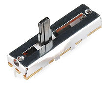
Sliding pot.
.png)

Regular pot - Thumb pot.
Trim pot - Multiturn pot.
The difference between both rotational pots is the amount of turns you need to go from its minimum resistance (usual 0Ω) to its maximum resistance R between terminals 1 and 2 (or 3 and 2) as defined in its symbol - see 'Working principle'. A normal (thumb) pot usually needs one to even less than one turn, while a trim pot needs 13 turns before it reaches its maximum. That's the reason why a trim pot is also called a multiturn pot.
Working principle
The idea of a potentiometer is actually really simple, but hard to explain easily. Generally, the resistance between terminals 1 and 3 is always fixed, no matter how much you turn the pot. If you buy a potentiometer of 10K for example, you will always measure a constant 10 kW (= kilo ohm) between the final terminals 1 and 3. To explain the functionality of terminal number 2, I need to draw its symbol in a different way as follows:

I splitted up the symbol into two variable resistors R1 and R2. That way you can immediately see why we are calling a potentiometer a voltage divider. For further explanations, I will call R the constant value of the potentiometer, so that mathematically R = R1 + R2. After rewriting this equation to R2 = R - R1, we see that R2 is depending on R1.
Take for example that you've turned the pot to one final position where R1 equals zero and thus R2 equals R. Now by slowly turning the pot to its other final position will R1 increase lineair with the angle of rotation (and thus R2 will decrease, such that the condition R = R1 + R2 is allways respected). Once you've reached the other final stop will R1 equal R and thus R2 will equal zero.
Use
FLAT CABLE
A flat cable or ribbon cable is especially used to make a wired electrical connection as evident and elegant as possible. Take for example the connection between the prosthesis and the glove (its main control) where you need to provide a connection cable consisting of 10 conductors, how would you get this done? You could simply bundle 10 different wires together with some cable ties, but that would be a mess and not elegant enough to wear the prosthesis. The solution is using a flat cable. Such cables exist of conducting wires running parallel to each other on the same flat plane. The number of conductors is usually restricted to a few standard values, including 4, 6, 8, 9, 10, 14, 15, 16, 18, 20, 24, 25, 26, 34, 37, 40, 50, 60, 64 and 80. A 10-pole flat cable is thus used in this project.
The spacing between two conductors is equal to 0.05inch or 1.27mm. That's kind of a problem because the distance between two holes on a PCB is equal to 1inch or 2.54mm. As a result is every flat cable equipped with an IDC socket, that can be plugged into a box header that is placed on the PCB.
Use