
BRUSHED DC MOTOR
A DC motor is an incredible piece of engineering that converts direct current (DC) electrical energy into mechanical energy. These kinds of motors are the most beneficial: they are light and small, you don't need to provide fuel, and they almost doesn't need any repairs. We can divide DC motors into two categories: brushed and brushless. A brushless motor has no brushes and so they don't need to be replaced timely due to wear and tear. But magic always comes with a price, and apparently a brushless motor is always more expensive than a brushed one. This paragraph descibes a brushed DC motor. A brushless DC motor is explained in my project Drone.

Small, low-cost DC motor
Working principle - Torque
A DC motor exist of a stator (the magnets) and a rotor (the rotating windings). The rotor comes in action by upcoming Lorentz forces F. Generally, a Lorentz force is caused by a current-carrying conductor that is placed into a (permanent) magnetic field B as shown in figure 1. This interesting phenomenon is applied in motors, where the current-carrying conductor is bent in the shape of a winding that can rotate about its axis as illustrated in figure 2. Hence, both upcoming Lorentz forces F produce a torque which turns the DC motor.

Figure 1

Figure 2
The higher the Lorentz force F, the higher the motor's torque*. In terms of a motor is torque T simply equal to F multiplied by the distance from the axis of the motor to the the point where the force is applied. That distance is also equal to the radius of the winding. In formula we get T=F·D/2, where D equals the diameter of the winding. However, one winding exists of two Lorentz forces on both sides, and thus the total torque of figure 2 becomes: T=2·F·D/2=F·D. Now you need to know that every DC motor in practice consists of more than one winding. Let's say that N represents the amount of windings inside a motor. The total torque of a motor is then the sum of all Lorentz forces applying on all windings, so that T=F·D·N.
*Just as a linear force is a push or a pull, a torque can be thought of as a twist to an object. Torque is somehow a 'rotational force'. From the picture at the right: Torque = Force · Distance.

The following GIF is an animation of figure 2 and makes the theory more clear. The magnetic field always goes from Nord (N) to South (S). The current always starts from the positive pole (+) of the power supply through the winding to the negative pole (-). Apparently, the winding will turn counterclockwise from the convention of figure 1 and 2. The direction of rotation in this animation is thus wrong.
A more practical interpretation can be given as follows: "You need a high twist or torque on a car's wheels to bring the car in motion. Once the car is driving at constant speed, the torque needed to keep the car moving is much lower."
Additional: How are the rotating windings connected with a static power source? A split ring commutator makes physical contact with two brushes, which connect to opposite poles of a power source to deliver positive and negative charges to the commutator. The commutator rubs against the brushes, and that's the reason why brushed DC motors experience wear and tear. If a motor seems to be broken, it will be most of the times the brushes that are worn out, but they can be replaced if you like. A brushless motor doesn't have brushes - as its name suggests - and operates differently.

Working principle - Speed
You already understand the idea of torque of a motor, that's a great start! But what about the rotational speed? The following paragraph gives an answer to this question and is really important, but also really difficult to understand. So read it a few times slowly until you definitely get the relation between torque and speed!
Important! At this moment you would probably tend to think: so the higher that force, the higher its torque, alright, but also the higher its speed, right? No no no, that's totally wrong! Keep in mind that the force F is not a constant, but dependent on the load attached to the motor (a car wheel for example). The higher the load (in weight, dimensions or friction), the more torque the motor need to keep it spinning, and thus a higher force F that will be produced by the motor. The motor can do this by drawing more current from the power supply applied to the motor**. Unfortunately, the speed of the motor will be lower due the higher load. So in general: If the load is higher, the torque of the motor will also be higher, but the speed will be lower! When the load becomes really high, the motor will generate its maximum torque (called stall torque) while the motor isn't even rotating, but only trying to hold the load. The motor will fail if the stall torque is lower than the desired torque. However, if there is no load anyway, the motor will spin at maximum speed (called no-load speed) and the torque will be really small, near to zero (there is always an 'internal load', namely the rotating windings inside the motor itself***). This paragraph can be translated into a curve: a typical Torque/Speed characteristic of a simple DC motor, as showed below. The torque will always increase if the speed decreases.

**The Lorentz force depends on numerous factors as you can see in its formula: F=I·l·B. This formula practically says that F will increase if the current I through the conductor increases.
***The formula T=F·D·N implies that an increase in the amount of windings N causes a higher torque T. The stall torque of a motor with more windings would thus be higher, but its no-load speed would be lower because more windings would induce a higher weight of the rotor and thus a higher 'internal load'.
Gear box
In general, a gear box is used to reduce the rotational speed. As a consequence, the torque will increase. Text...
ACCELEROMETER
An accelerometer is an electronic device that measures the acceleration experienced by an object. Acceleration of an object is caused by changing the speed of the object with respect to time. Take for example a car you're driving at constant speed of 50 km/h. In this situation you wouldn't feel any forces on your body and you're free to move in the car. Suddenly you push the brakes and you slowly go from 50 km/h to rest. While you're slowing down, you will feel a force pushing you forwards. That force is caused by the acceleration of the car (Newton's Second Law). If you had an accelerometer in your car, the device would give you zero acceleration while driving at constant speed, and give you the exact acceleration while slowing down. Maybe you would think to yourself right now: is that measurement really useful to us?
No, it isn't. First of all, small accelerometers in electronics (called MEMS accelerometers like the MPU6050 or ADXL335 or ...) aren't precise enough to measure lineair acceleration. Furthermore, the idea of measuring lineair acceleration in case of the accelerometer on my hand (the main control of this project) would be pointless, because my hand stays in rest the whole time. So why am I using an accelerometer anyway? The answer is 'gravity'. Remember that gravity also causes gravitational acceleration, which means you can also use an accelerometer for measuring the orientation of a stationary* object in space. As a result, I'm using the accelerometer to measure the orientation of my hand.
*The object must be stationary. Otherwise, the measurement of its orientation would be interfered with its lineair acceleration.
How does an accelerometer work (for orientation purposes)?
First, I explain the working principle of an accelerometer by using the analogy of a ball in a box. Figure 1 gives the situation while the acceleremeter (= the 3D box with dimensions XYZ) is placed horizontal.

Figure 1

Figure 2
If you tilt the accelerometer 45 degrees clockwise for example as in figure 2 is showed, the ball will pressure less on the green surface (Z-) and more on the blue surface (X-). From the measurement of pressure on each surface we can determine the orientation of the accelerometer.
Anyway, an accelerometer in reality doesn't exist of a ball in a box. The box is replaced by fixed plates, the ball by a moving plates, and where difference in capacitance between them needs to be measured (instead of a pressure from the analogy). These accelerometers are called MEMS accelerometers, where MEMS stands for 'Microelectromechanical Systems'. Text
FLEX SENSOR
In my project 'Hand Prosthesis', I discussed potentiometers and told you that a potentiometer can be used as a variable resistor. A variable resistor on itself is actually a two-terminalled component. The most common are light-dependent resistors (LDR), force-sensitive sensors, and flex sensors. I will explain this last variant (you can also call it a flex-dependent resistor if you want).

LDR
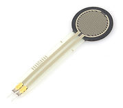
Force Sensor

Flex Sensor
Working principle
Text
Use - Let's do some math
Making a voltage divider with a variable resistor sounds easy: Pick another fixed resistor and place it in serie with the variable one, as illustrated in the figure below. The voltage output Vout across R2 is dependent on the value R1. But how do you have to decide the fixed value for R2? Most people will take a 10kohm without worrying about it. 10Kohm is indeed a good value in general, but actually you can choose a much better value in order to have a wider range of different output voltages across R2. The formula for R2 is really easy, and I will derive it together with you.

To make the notations a bit easier, I will call R2 the variable x. The minimum value for R1 is called a, and its maximum is called b (a and b are thus only parameters).
In general, we know that:
.png)
The minimum and maximum voltage outputs are thus respectively
.png)
.png)
The difference DV between them can be written as
.png)
Now, we want to know what value x has to be such that the difference delta V becomes largest. This is called an extremum problem in mathematiques and can be solved by solving the following equation:

Solving the equation gives the following easy formula
.png)
Conclusion: You can calculate R2 by using the equation above. Therefore, you need to measure the minimum and maximum resistance of the variable resistor you use first. Next, multiplying both results and taking the square root of that result will give you the desired resistance for the fixed resistor in serie.
Practical example:
NIMH BATTERY vs.
LIPO BATTERY
Batteries are the wireless version of a power supply. They are like everywhere around you, like in your smartphone, laptop, and even in a mathematian's favourite toy: a calculator. We have two different types in general: single-use and rechargeable. The rechargeable batteries can be divided into NiMH (Nickel Metal Hydride) and lithium-ion batteries such as a LiPo (Lithium Polymer) battery. Lithium batteries have less weight, but NiMH batteries are more robust. LiPo batteries are explained in the paragraph down below, after I discussed NiMH batteries here in particular.
NiMH Battery
All rechargeable batteries (AAA, AA, etc...) you have at home are NiMH batteries. Such one battery is called a battery cell. Multiple cells in series are called a battery pack. One NiMH cell has a nominal voltage of 1.2V. So if you see a 6-cell NiMH battery pack, you know immediately that this battery pack has a nominal voltage of 7.2V (= 6 x 1.2V).
Foto Batterijen in het huishouden
Properties
I'm not going to expand on the working principle of a battery, that's the job of a chemical engineer. More interesting is the way we have to use and treat this batteries.
Charging Process
test
NIMH BATTERY vs.
LIPO BATTERY
A NiMH battery has one big problem: its high weight/capacity ratio. Luckily, we have the scientist and invented lithium-ion batteries to solve this problem. But mind you, every advantage carries his disadvantage, so why are we still using NiMH battaries in household applications? Well, lithium batteries are kinda dangereous and less robust than NiMH ones...
LiPo Battery
All rechargeable batteries in smartphones, electric cars or bikes, etc. are LiPo batteries because of its low weight/capacity ratio in contrast to a NiMH one. Such as the NiMH batteries, we can also speak about a LiPo battery cell. Multiple cells in series are called a battery pack. One LiPo cell has a nominal voltage of 3.7V (More than three times the nominal voltage of a NiMH cell!). So if you buy a 3-cell LiPo battery pack (indicated with 3S), you know immediately that this battery pack has a nominal voltage of 11.1V (= 3 x 3.7V).